NPT fittings, also known as National Pipe Thread fittings, are a type of fitting commonly used in industrial, automotive, and plumbing applications. They are designed to provide a secure, leak-free connection for fluid and gas systems, and are known for their durability and versatility.
NPT fittings are designed to connect to pipes or hoses that have NPT threads, which are a specific type of thread that is tapered and designed to create a tight seal when connected. NPT fittings come in a variety of sizes, styles, and materials, which allows them to be used in a wide range of applications.
One of the main advantages of NPT fittings is their ability to handle high pressures and temperatures. They are typically made from brass, stainless steel, or carbon steel, which are strong and durable materials that can withstand the high pressures and temperatures found in industrial, automotive, and plumbing applications. Additionally, NPT fittings are designed to be reusable, which means they can be disconnected and reconnected multiple times without losing their seal.
Another advantage of NPT fittings is their versatility. They come in a variety of sizes and styles, which allows them to be used in a wide range of applications. For example, they are commonly used in compressed air systems, fuel systems, water systems, and oil systems. They can also be used to connect pipes, hoses, valves, and other components together.
When it comes to selecting NPT fittings, the first thing to consider is the size of the fitting. NPT fittings are available in a range of sizes, from 1/8″ to 2″, with 1/8″ being the smallest and 2″ being the largest. The size of the fitting you choose will depend on the size of the pipe or hose you are using, as well as the pressure and flow rate of the fluid you are working with.
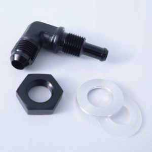
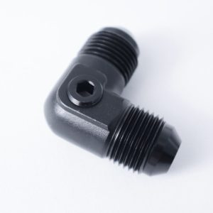
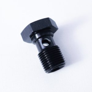
Another important factor to consider when selecting NPT fittings is the type of fitting. There are a few different types of NPT fittings available, including straight, elbow, and tee fittings. Straight fittings are used to connect two pipes or hoses together, while elbow fittings are used to change the direction of a pipe or hose. Tee fittings are used to split a line into two or more lines.
Lastly, it’s important to consider the material of the fitting. NPT fittings are commonly made from brass, stainless steel, or carbon steel. Brass fittings are corrosion-resistant and suitable for most applications. Stainless steel fittings are stronger and more durable, and are typically used in high-pressure and high-temperature applications. Carbon steel fittings are strong and durable and typically used in heavy-duty industrial applications.
In conclusion, NPT fittings are a popular choice for industrial, automotive, and plumbing applications for their strength, durability, and versatility. They are designed to handle high pressures and temperatures, and come in a variety of sizes, styles, and materials. When selecting NPT fittings, it is important to consider the size, type, and material of the fitting to ensure that it is suitable for your application.