When it comes to high-performance engines, maintaining the right operating temperature is critical. Overheating can lead to severe engine damage, reduced efficiency, and premature wear. One of the most effective ways to keep engine oil within optimal temperature ranges is through the use of an engine oil cooler. Proper installation and hose routing are essential to ensure that the oil cooler functions effectively, keeping the engine lubricated and cooled even during demanding driving conditions.
In this blog post, we’ll discuss the key considerations for engine oil cooler installation and hose routing, helping you ensure a smooth and efficient setup that maximizes engine longevity.
1. Choosing the Right Engine Oil Cooler
Before we dive into the installation and routing process, it’s important to select the right oil cooler for your engine. There are two main types of oil coolers: air-to-oil coolers and water-to-oil coolers.
- Air-to-oil coolers are the most common and are mounted in front of the radiator or on the side of the engine bay to allow air to pass over them. They’re usually used in motorsport and street applications where cooling efficiency is critical but external coolant lines aren’t an option.
- Water-to-oil coolers are more commonly found in OEM setups, where engine coolant circulates through the cooler to transfer heat from the oil. These are more compact but often require more complex plumbing.
For most aftermarket applications, air-to-oil coolers are easier to install and offer excellent cooling performance for most performance builds. However, selecting the right size and capacity based on your engine’s power output and intended use is crucial.
2. Location of the Oil Cooler
The placement of the oil cooler is critical for its efficiency. Here are some key considerations for optimal positioning:
- Clear Flow of Air: Ideally, the oil cooler should be placed in a location where there’s a constant flow of cool air. This is typically in front of the radiator, where airflow is highest. If the cooler is placed too far from the airflow, it won’t dissipate heat efficiently.
- Avoid Heat Sources: The cooler should not be positioned near other components that generate a lot of heat, like the exhaust manifold or turbocharger. Placing it in a heat-absorbing location can cause the oil to warm up unnecessarily, defeating the purpose of the cooler.
- Accessibility for Maintenance: Choose a spot that makes the cooler and its connections easy to access for maintenance. This includes checking the oil lines and ensuring there’s room to clean or replace the cooler if needed.
3. Oil Cooler Mounting
Once you’ve chosen the ideal location, the next step is mounting the oil cooler. Most aftermarket oil coolers come with brackets and mounting hardware for easy installation. However, if you’re fabricating your own mounts, make sure the cooler is securely attached to prevent vibrations or movement that could damage the cooler or the oil lines.
- Secure and Vibration-Free: The oil cooler should be securely mounted with rubber grommets or isolators to minimize vibrations. Excessive vibrations can cause the cooler or lines to crack over time, leading to leaks.
- Allow Room for Expansion: Ensure there’s enough space around the cooler for airflow, as well as to accommodate any future upgrades or changes to the engine bay.
- Mount with Ports Facing Up: Although not an absolute requirement for proper operation, it is highly recommended to mount the oil cooler with the ports facing up. This ensures that the oil cooler does not drain back to the engine while not in operation, ensuring that oil gets to the engine internals quickly. If the oil cooler drains during engine off, it may require that the oil cooler fills completely before oil gets to the engine, meaning that for those crucial first few seconds of engine start it will not have any oil pressure.
4. Proper Hose Routing
The next crucial step in oil cooler installation is the correct routing of the hoses. The goal here is to ensure smooth oil flow while avoiding sharp bends, kinks, or unnecessary pressure drops.
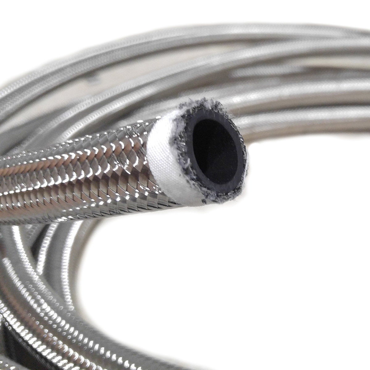
- Use High-Quality Hoses: Choose oil-resistant, high-quality hoses that are designed to handle the high temperatures and pressures present in the engine oil system. Stainless steel braided hoses are popular due to their durability, resistance to abrasion, and heat protection.
- Avoid Sharp Bends: When routing hoses, avoid sharp angles or tight bends that can restrict oil flow. Excessive bends can cause the oil to move sluggishly, reducing the cooling efficiency of the system.
- Minimize Length: Try to keep the hoses as short as possible. Longer hoses increase friction and can cause a slight pressure drop, reducing the oil flow to the cooler. If longer lines are required, make sure they’re smooth and wide to allow for proper flow.
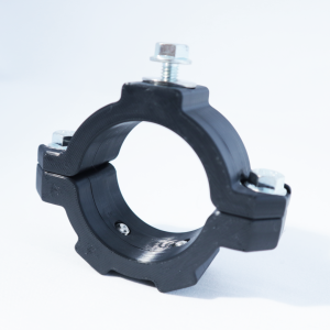
- Secure the Hoses: Use clamps or ties to secure the hoses along their route, ensuring they are firmly held in place to avoid rubbing against other engine components. This is especially important in high-heat environments, where friction can cause hoses to wear out faster.
- Insulate if Necessary: If hoses must pass near hot engine components, like exhaust manifolds or turbochargers, use heat sleeves or protective insulation to protect the hoses from extreme heat. This will ensure that the oil stays at a stable temperature and won’t be adversely affected by surrounding hot surfaces.
5. Oil Flow Direction
Most oil coolers are designed to flow in one direction: oil enters from the engine’s oil pump and exits through the cooler before returning to the engine. Double-check the cooler’s inlets and outlets to ensure that you’re connecting the hoses correctly. Improper flow direction can result in ineffective cooling, and in some cases, it could damage the cooler or engine.
- Engine to Cooler to Engine: Ensure the oil flows from the engine, through the cooler, and back into the engine’s oil system. This setup ensures that the oil is properly cooled before returning to the engine’s lubrication system.
6. Testing the System
Once the oil cooler is installed and the hoses are routed, it’s time to test the system for leaks and proper function. Check all connections and hoses for signs of leaks and tighten any fittings as needed. Start the engine and monitor the oil temperature with a gauge to ensure that the cooler is doing its job.
- Leak Testing: Before running the engine at full temperature, perform a dry run by starting the engine and checking the system for leaks. It’s crucial to catch any small leaks before they become bigger problems.
- Monitor Oil Temperature: After ensuring there are no leaks, run the engine at operating temperature and monitor the oil temperature. It should stay within the recommended range — typically between 180°F and 220°F (82°C to 104°C) for most performance engines. If the temperature rises significantly, it could indicate that the cooler is not installed correctly or the hoses are restricted.
7. Regular Maintenance
Lastly, it’s important to periodically inspect the oil cooler, hoses, and fittings. Over time, heat and pressure can take their toll, leading to potential wear and tear. Regularly check for signs of leaks, hose damage, or any obstruction in the cooler that could reduce its efficiency. Keep the cooler clean and free of debris to ensure optimal airflow.
Conclusion
Proper engine oil cooler installation and hose routing are vital to keeping your engine running smoothly, especially in high-performance or heavy-duty applications. By selecting the right cooler, mounting it securely, routing the hoses carefully, and ensuring everything is sealed and functioning correctly, you can significantly improve your engine’s ability to maintain an optimal operating temperature. This results in better performance, enhanced longevity, and a reduction in the risk of catastrophic engine failure due to overheating.
Whether you’re building a track car, a tow rig, or a high-performance street machine, investing time in the proper installation and maintenance of your engine oil cooler will pay off in the long run.